1
/
of
4
Uploader
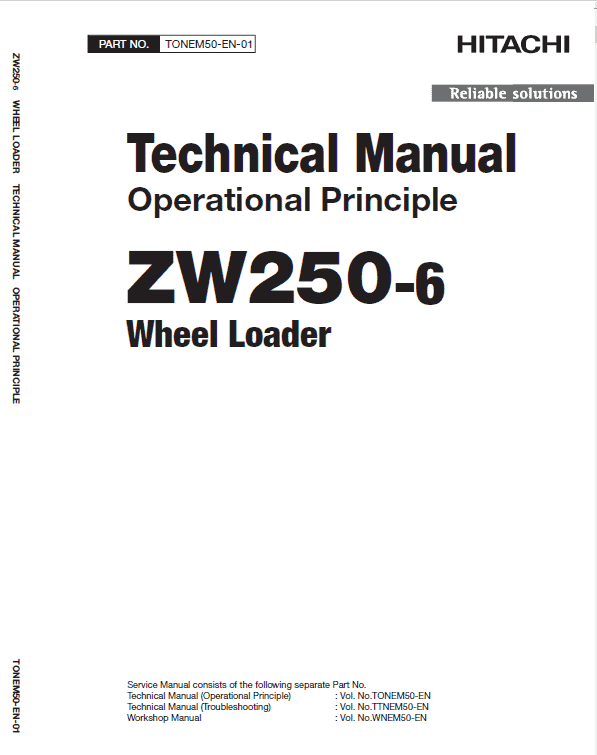
Hitachi ZW250-6 Wheel Loader Service Repair Manual Workshop Guide
Hitachi ZW250-6 Wheel Loader Service Repair Manual Workshop Guide
Regular price
$60.00 USD
Regular price
Sale price
$60.00 USD
Taxes included.
Shipping calculated at checkout.
Quantity
.
In Stock
Couldn't load pickup availability
Format : PDF
SUPPLIED AS DOWNLOADABLE LINK
Service Repair Manual (Troubleshooting) : Vol. No.TTNEM50-EN (496 Pages)
Operation Manual : Vol. No.TONEM50-EN (545 Pages)
Workshop Manual : Vol. No.WNEM50-EN (444 Pages)
Circuit diagram: 21 Pages
Description
Hitachi ZW250-6 Wheel Loader Service Manual
The manual is applicable for the Hitachi ZW250-6
Wheel Loader
Model
Format: PDF
Language: English
Service Manual consists of the following:
For Model ZW250-6 as mentioned above:
Service Manual (Troubleshooting) : Vol. No.TTNEM50-EN (496 Pages)
Operation Manual : Vol. No.TONEM50-EN (545 Pages)
Workshop Manual : Vol. No.WNEM50-EN (444 Pages)
Circuit diagram: 21 Pages
Table of Content of the Workshop Manual
SECTION 1 GENERAL
Group 1 Precautions for Disassembling and
Assembling
Group 2 Tightening
Group 3 Painting
Group 4 Bleeding Air
Group 5 Preparation
SECTION 2 MAINTENANCE STANDARD
Group 1 Body
Group 2 Front Attachment
SECTION 3 BODY
Group 1 Cab
Group 2 Counterweight
Group 3 Center Hinge
Group 4 Engine
Group 5 Radiator Assembly
Group 6 Hydraulic Oil Tank
Group 7 Fuel Tank
Group 8 Pump Device
Group 9 Control Valve
Group 10 Pilot Valve
Group 11 Brake Charge Valve
Group 12 Manifold Valve
Group 13 Solenoid Valve
Group 14 Flow Regulator Valve
Group 15 Cooling Fan System
Group 16 Ride Control Accumulator
Group 17 Battery Disconnect Switch
Group 18 Aftertreatment Device
Group 19 DEF Tank
Group 20 Coolant Control Valve
Group 21 DEF Supply Module
Group 22 Exterior Components
Manual guide composition
Hitachi ZAXIS ZW250-6 service manual consists of the Troubleshooting and the Workshop Manual.
Information included in the Service Manual: Technical information needed for redelivery and delivery, operation and activation of all devices and systems, operational performance tests, and troubleshooting procedures.
Information included in the Workshop Manual: Technical information needed for maintenance and repair of the machine, tools and devices needed for maintenance and repair, maintenance standards, and removal / installation and assemble / disassemble procedures.
Fault Code
Trouble
Symptoms in Machine Operation When Trouble Occurs.
MPDr.
CUMMINS
27-4
2272
EGR Valve Position Circuit – Voltage Below Normal, or Shorted to Low Source
EGR valve actuation will be disabled.
91-0
148
Accelerator Pedal or Lever Position Sensor Circuit – Abnormal Frequency, Pulse Width, or Period
Severe derate in power output of the engine. Limp home power only.
91-1
147
Accelerator Pedal or Lever Position Sensor Circuit – Abnormal Frequency, Pulse Width, or Period
Severe derate in power output of the engine. Limp home power only.
91-2
1242
Accelerator Pedal or Lever Position Sensor 1 and 2 – Data Erratic, Intermittent, or Incorrect
Engine will only idle.
91-3
131/1358
Accelerator Pedal or Lever Position Sensor 1 Circuit – Voltage above normal, or shorted to high source
Severe derate in power output of the engine. Limp home power only.
SUPPLIED AS DOWNLOADABLE LINK
Service Repair Manual (Troubleshooting) : Vol. No.TTNEM50-EN (496 Pages)
Operation Manual : Vol. No.TONEM50-EN (545 Pages)
Workshop Manual : Vol. No.WNEM50-EN (444 Pages)
Circuit diagram: 21 Pages
Description
Hitachi ZW250-6 Wheel Loader Service Manual
The manual is applicable for the Hitachi ZW250-6
Wheel Loader
Model
Format: PDF
Language: English
Service Manual consists of the following:
For Model ZW250-6 as mentioned above:
Service Manual (Troubleshooting) : Vol. No.TTNEM50-EN (496 Pages)
Operation Manual : Vol. No.TONEM50-EN (545 Pages)
Workshop Manual : Vol. No.WNEM50-EN (444 Pages)
Circuit diagram: 21 Pages
Table of Content of the Workshop Manual
SECTION 1 GENERAL
Group 1 Precautions for Disassembling and
Assembling
Group 2 Tightening
Group 3 Painting
Group 4 Bleeding Air
Group 5 Preparation
SECTION 2 MAINTENANCE STANDARD
Group 1 Body
Group 2 Front Attachment
SECTION 3 BODY
Group 1 Cab
Group 2 Counterweight
Group 3 Center Hinge
Group 4 Engine
Group 5 Radiator Assembly
Group 6 Hydraulic Oil Tank
Group 7 Fuel Tank
Group 8 Pump Device
Group 9 Control Valve
Group 10 Pilot Valve
Group 11 Brake Charge Valve
Group 12 Manifold Valve
Group 13 Solenoid Valve
Group 14 Flow Regulator Valve
Group 15 Cooling Fan System
Group 16 Ride Control Accumulator
Group 17 Battery Disconnect Switch
Group 18 Aftertreatment Device
Group 19 DEF Tank
Group 20 Coolant Control Valve
Group 21 DEF Supply Module
Group 22 Exterior Components
Manual guide composition
Hitachi ZAXIS ZW250-6 service manual consists of the Troubleshooting and the Workshop Manual.
Information included in the Service Manual: Technical information needed for redelivery and delivery, operation and activation of all devices and systems, operational performance tests, and troubleshooting procedures.
Information included in the Workshop Manual: Technical information needed for maintenance and repair of the machine, tools and devices needed for maintenance and repair, maintenance standards, and removal / installation and assemble / disassemble procedures.
Fault Code
Trouble
Symptoms in Machine Operation When Trouble Occurs.
MPDr.
CUMMINS
27-4
2272
EGR Valve Position Circuit – Voltage Below Normal, or Shorted to Low Source
EGR valve actuation will be disabled.
91-0
148
Accelerator Pedal or Lever Position Sensor Circuit – Abnormal Frequency, Pulse Width, or Period
Severe derate in power output of the engine. Limp home power only.
91-1
147
Accelerator Pedal or Lever Position Sensor Circuit – Abnormal Frequency, Pulse Width, or Period
Severe derate in power output of the engine. Limp home power only.
91-2
1242
Accelerator Pedal or Lever Position Sensor 1 and 2 – Data Erratic, Intermittent, or Incorrect
Engine will only idle.
91-3
131/1358
Accelerator Pedal or Lever Position Sensor 1 Circuit – Voltage above normal, or shorted to high source
Severe derate in power output of the engine. Limp home power only.
Share